These tools bring together the analysis of steady-state errors in systems with unit feedback and the main controller design techniques used in introductory courses, both in the time and frequency domains, covered in eleven tools. It covers aspects of analytical design of simple PID-type controllers for systems without delay (basically pole cancellation and pole assignment), heuristic or approximate designs for systems with delay (Ziegler-Nichols and lambda method), the inclusion of filters in the reference to decouple the reference tracking problem and disturbance rejection, the classical frequency design of phase-lead and phase-lag controllers in the Bode diagram, and also the analytical design of these kind of compensators based on typical frequency response specifications.
Steady state error in unit feedback control systems
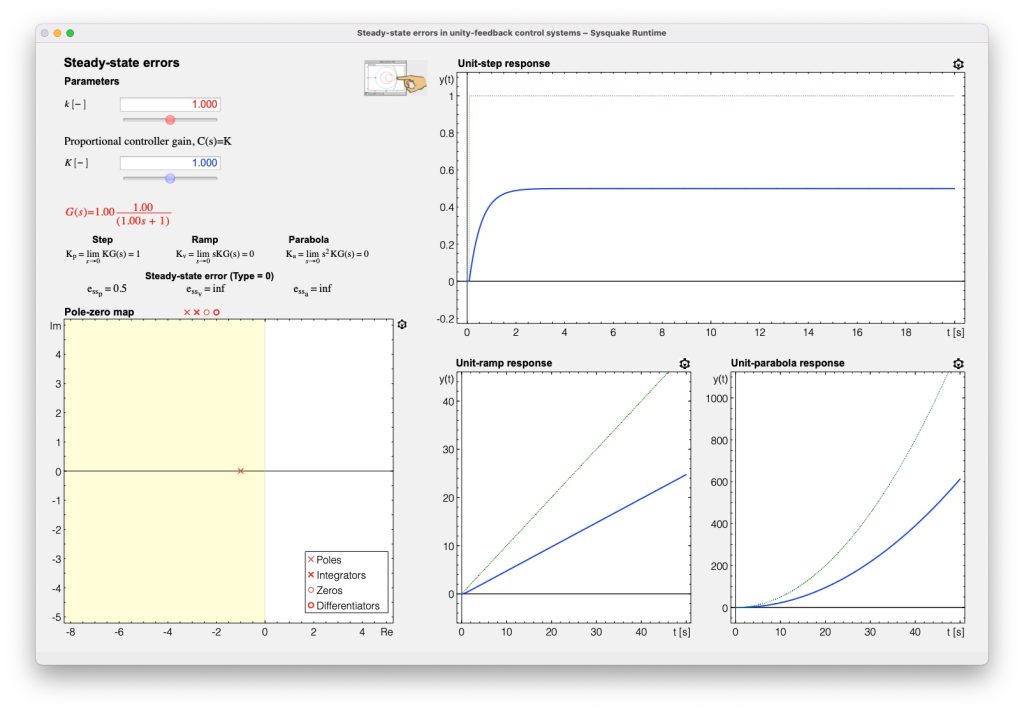

The main objective of this card is to analyze steady-state errors of unit feedback control systems when different test inputs are are used as reference in the closed loop. It is therefore possible to visualize the errors in time response graphs and to analyze the value of the main steady-state error constants.
Proportional, integral and derivative (PID) controllers
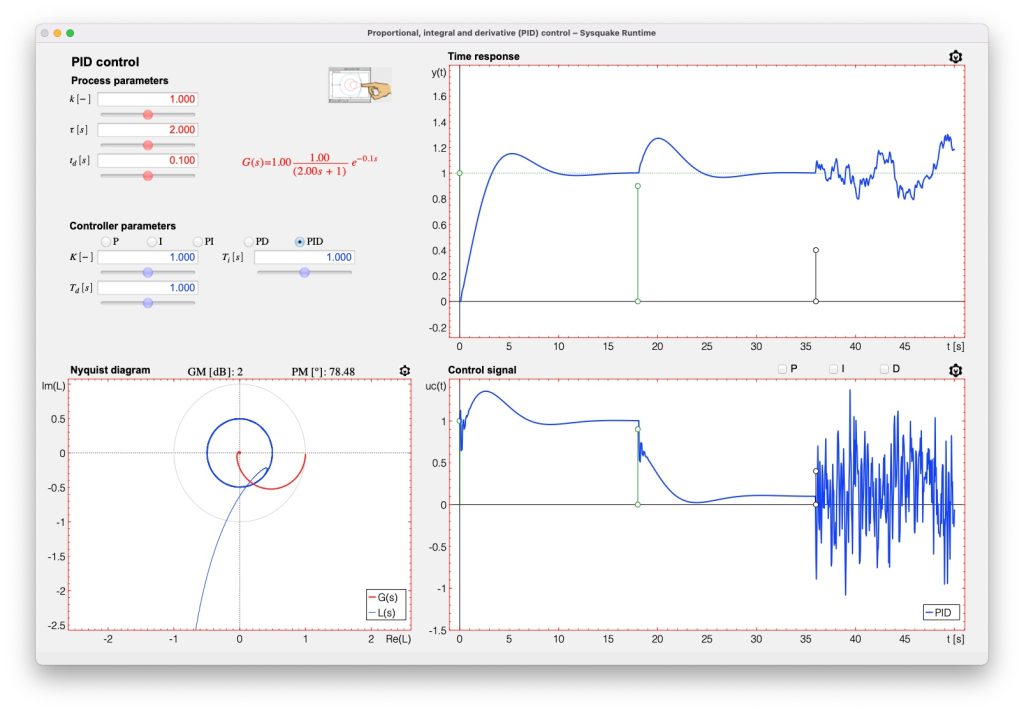
This tool is devoted to analyzing the effect of the three control actions which a PID controller implements, both in the time and frequency domains. In the time domain it is possible to visualize the contribution of each of the terms in the control signal. Moreover, response to step changes in the reference and the load disturbance are possible to analyze, as well as the influence of noise. The representation selected to analyze the frequency response is the Nyquist diagram, which also provides GM and PM for the selected parameters. Different ideal PID structures can be selected: P, I, PI, PD and PID.
Phase-lag and phase-lead compensators
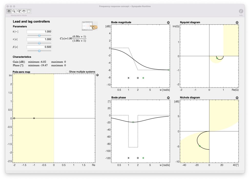
This tool is devoted to analyzing the effect of phase-lead and phase-lag compensators on the frequency response. The effect of the location and relative position of the pole and the zero of the compensator can be easily analyzed in the Bode, Nyquist and Nichols diagrams, and thus, their effect when used as controllers in frequency design methods using PM and GM specifications.
PI control of first-order systems without time delay by pole placement
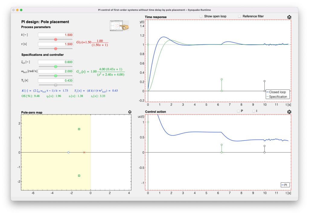
This card is devoted to studying the simplest pole placement design, that is a PI controller for a first-order system without time delay. This helps the reader to easily understand the concept of pole placement and also the role of reference filters in the closed-loop time response.
PI control of first-order systems by pole cancellation
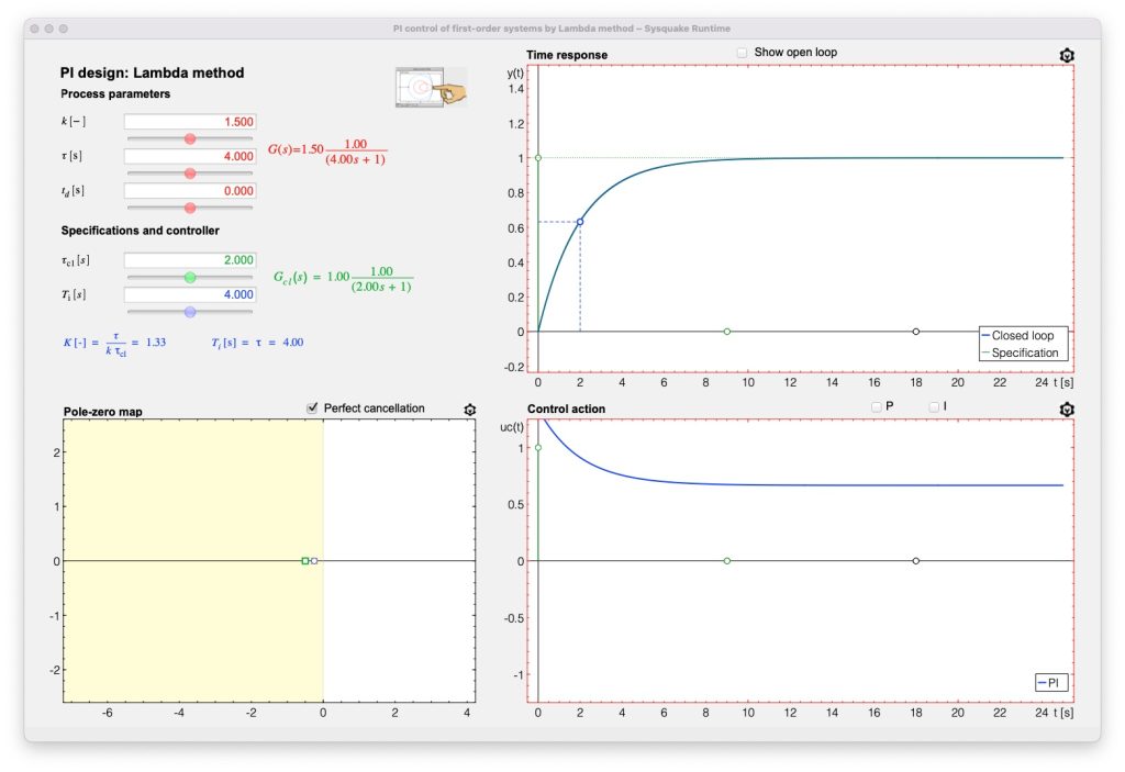
This tool is devoted to understanding the pole-zero cancellation design, using a PI for controlling a first-order system without and with time delay. The advantages and drawbacks of the technique are analyzed using illustrative examples and the corresponding interactive tool.
PID control based on the open-loop Ziegler-Nichols tuning rules
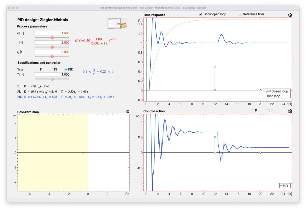
This tool is devoted to studying the Ziegler-Nichols PID tuning rules based on the reaction curve method. This is a heuristic method through which a first approxi- mation of PID control parameters can be obtained for overdamped systems with time delay. The interactive tool is very useful to analyze the closed-loop response achieved using the PID parameters provided by the rules, in terms of setpoint tracking, load disturbances rejection and noise amplification. The PID Ziegler Nichols tool also implements setpoint filtering (2-DoF control) as explained in the card, helping to decouple tracking and disturbance rejection problems, so that the design of the PID controller can be oriented to the disturbance rejection problem, while avoiding noise amplification in the loop.
Classical design of phase-lag controllers in frequency domain with two specifications
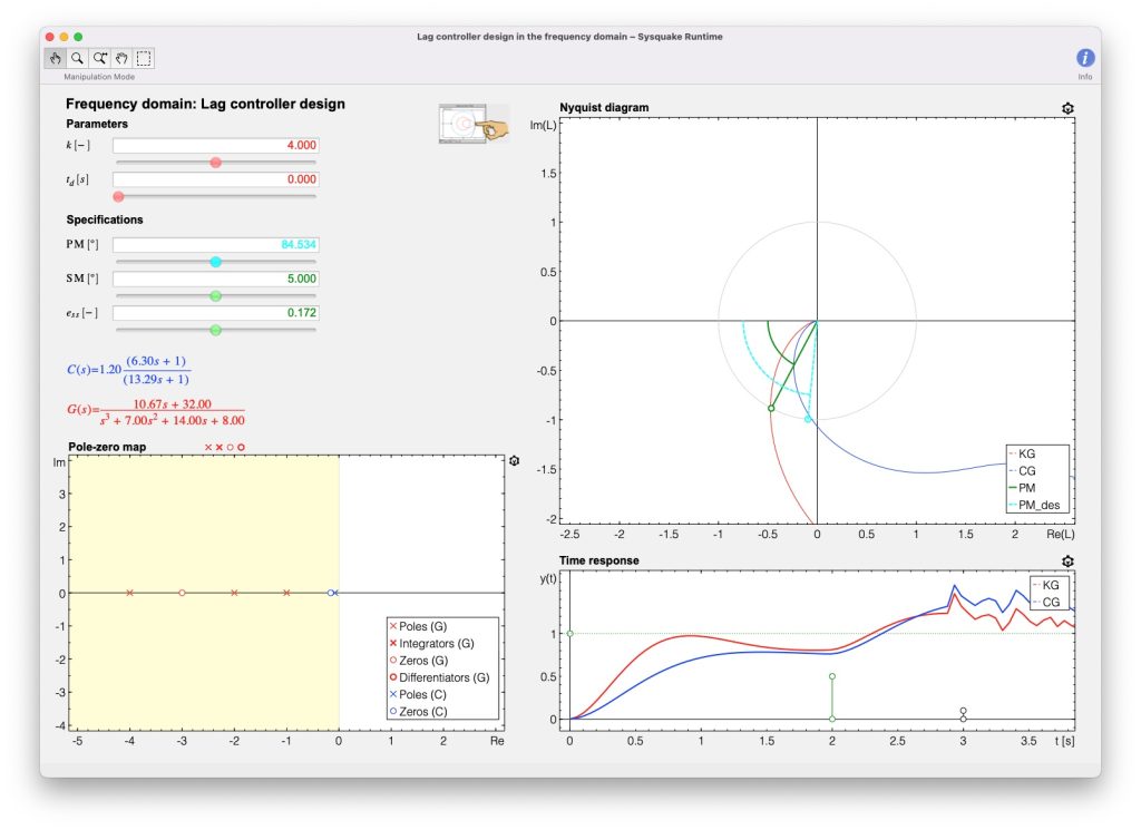
This tool deals with the classical design of phase-lag compensators in the frequency domain based only on two specifications: steady-state error and phase margin. The underlying concepts and approximations are graphically treated, so that the user can verify all the steps explained in control textbooks and interactively analyze if the specifications can be met.
Classical design of phase-lead controllers in frequency domain with two specifications
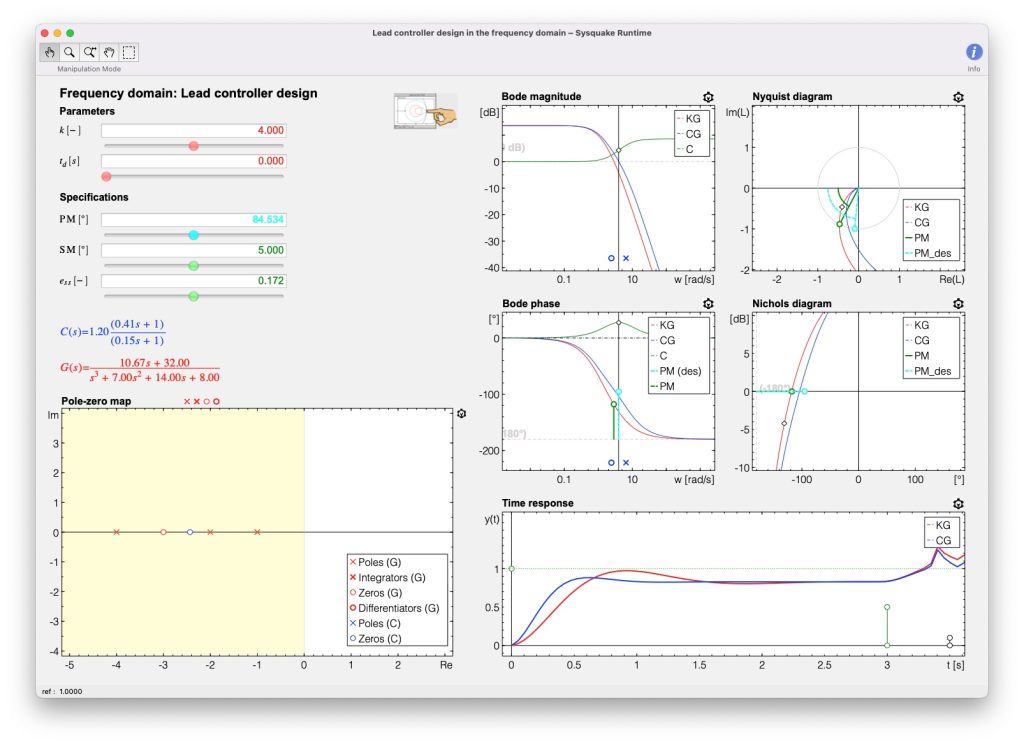
This tool deals with the classical design of phase-lead compensators in the frequency domain, using only two specifications: steady-state error and PM. The underlying concepts and approximations are graphically treated, in such a way that the user can verify all the steps explained in the summary of fundamental theory and interactively analyze if the specifications can be met. This interactive tool is very similar to the f design lag in terms of its distribution and interactive elements, although the design seeks different objectives.
Design of phase-lead or phase-lag controllers in the frequency domain with three specifications
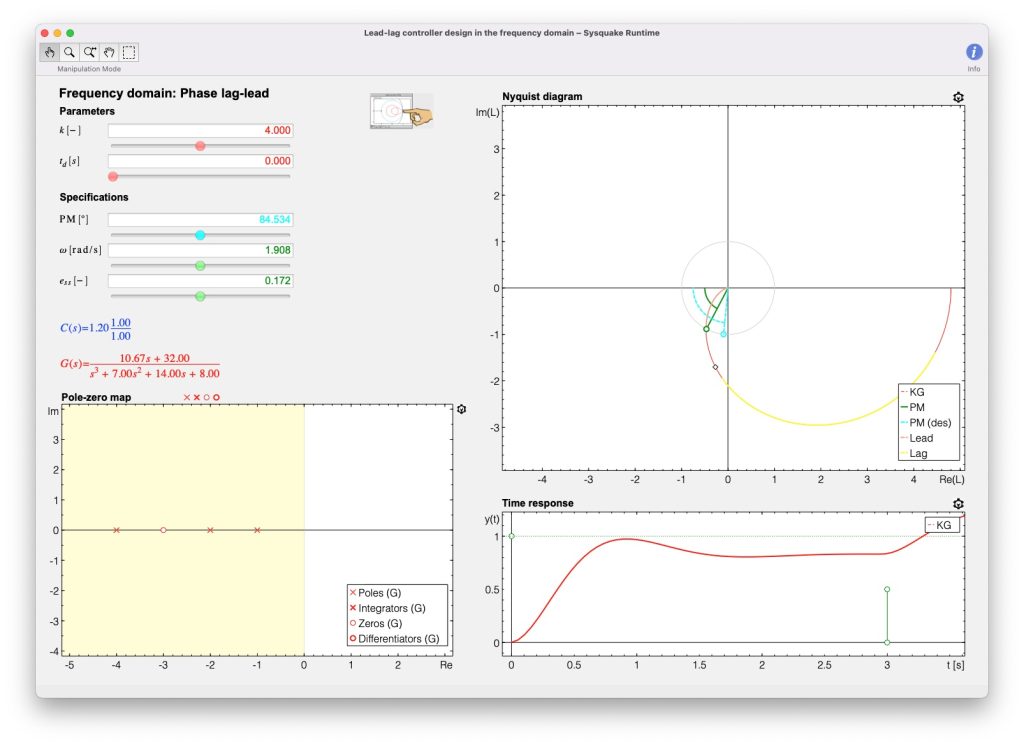
This tool deals with the design of phase-lead or phase-lag compensators imposing three specifications, one related to steady-state and two to the relative stability and speed of response. This provides analytical formulas to directly design the controller, what limits the possibilities of interactive tools to graphically show the design and obtained results. It can be a starting point for loop shaping design and moreover the tool provides interesting information about the conditions for which to fulfill the specifications either with a phase-lead or a phase-lag compensator.