User's guide of Neotrie VR Multiplayer
BETA VERSIONS UNTIL 4.7.3
LINK TO GUIDE FROM VERSION 4.74
Download our new flyer.
Check the latest news of the software.
Please follow our YouTube channel to be aware of all the news.
Check the user guide for the previous version Neotrie VR 2021.

Software installation (Quest Version)
- Set up your Quest following these instructions.
- Request access to the Neotrie beta channel from the contact form, indicating the email assigned to your Meta quest headset.
- Accept the invitation from Virtual Dor to access the Neotrie beta channel. To do this, search for email from do_not_reply@mail.oculus.com. You will need to be logged in to your Facebook/Oculus/Meta account on the same browser on your phone or computer for the opt-in link to work:

Once this invitation is accepted, Neotrie will automatically appear available in the application gallery in your Quest, after restarting the headset, if necessary.
Casting from Quest to a PC or phone or tablet
To take broadcast from the Quest on a computer open in Google Chrome http://www.oculus.com/casting

On your Quest, press the sharing red button.

The share option allows you to share a photo or video on Facebook or get on a computer with a USB cable.
Software installation (Only PC Version)
- Update Windows.
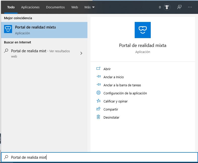
- (Only for Windows Mixed Reality headsets) In Cortana’s searcher of your desktop, look for “Windows Mixed Reality” and install it.
- If Oculus Rift, download Neotrie VR from the library of Rift experiences.
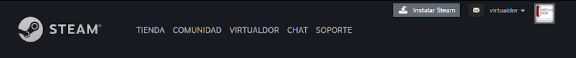
- In other cases, register at STEAM and keep login for the next steps.
- Install STEAM: press on button at the right top corner.
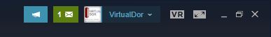
- Open Steam and then install SteamVR (click on button “VR” on the right top corner).
- (If Windows Mixed Reality) Look for Windows Mixed Reality for SteamVR and install it:
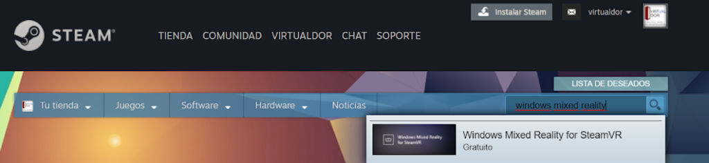
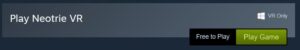
- Download Neotrie VR from the store of STEAM, by pressing on "Play Game".
Login
Once registered on the Neotrie website, you can access your user and content, from within the game. You can skip login if you are going to stay as a Beginner player. Login is needed to have chat voice available in the Multiplayer mode.

Licenses
These are the different types of licenses available. You can click here to see the prices of each one. The corresponding license can be selected in Player Settings. In the multiplayer mode, you will need to be all the players in the same license to see the same tools.

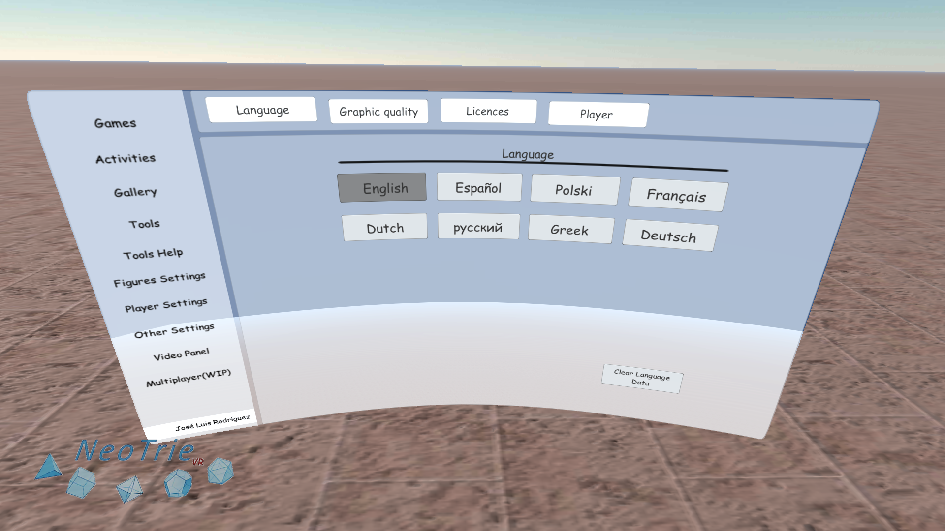
Player settings
Press trackpad or button B or Y, and touch Configuration button (see below) to acess to the Main menu and open the tab "Player Settings".
Language
Choose a language (some parts of the multiplayer version are only in English)
Graphics quality
Choose a graphic quality level. Some huge figures may require low quality level or hiding vertices or edges in the Figure settings.

Player
Pass your virtual hand on the buttons "boy" or "girl" to choose an avatar, hair color, etc.
Write your name in the box "Player name".

Take the camera (black rectangle) on the table to see what you look like. Make sure you have a personal name to properly access the multiplayer mode voice chat.

Guide
Choose a guide, Hypatia or Euclid, to show you how to use the basic actions of your hands, teleport and use some geometric tool.


You can also see videos of first steps and tool helps in the box Activities in the scene.
Multiplayer mode (beta)
This mode allows several players to play in the same scene. It is reccomended to write your own name in Player Settings.

The host creates a public or private lobby. The other players join it by pressing the "Quick Join Public Lobby" or "Join Lobby" with the code facilitated by the host.

The host can choose "Teacher" option to have more control on the scene. In this mode, the other players will have restrictions. For instance, they will not be able to delete or load activities or neot, hide geometric figures, etc.

All players are blocked until the host and the players are connected. The scene is cleared in each player when entering a lobby.

Any player, except the host, can leave the lobby, by pressing the button "Exit Lobby".
First steps: Hand actions
With your hands you can create any figure with vertices, edges, faces, as well as edit any of these elements.

To select any of these options maintain touched the Trackpad or buttons A, X and then, pass the hand (the pink point on your hand) over the different symbols to select them. The symbol will change to white, and also in your back hand.
- Create vertices and edges: Press the Trigger Button to create vertices at the Pink Dot Pointer. To create an edge between two vertices press the Trigger Button on one vertex and then, the second vertex. To create a face, maintain pressed and touch 3 or more vertices of the face.
- Faces: This permits to create a face by selecting the boundary edges keeping the Trigger Button pressed. It also creates a disk by touching a circle.
- Edit: Press the Trigger Button on a vertex, edge or face, and keep it pressed to move it.
- Erase: Click over the vertice, edge, face or any single element that you want to delete.
- Move: Move a figure. Having this transform action on both hands, allows you to resize the complete figure.
- Grab: Rotate a figure.
- Draw: Use this action to create free drawings, by keeping pressed the Trigger Button.
- Extrude to build prisms and pyramids from any face.
- Redo: Press the trigger button on a geometric element to redo its position, translation or rotation, or changed color. Press on the air to redo deleted elements.
Quick access to menu
Press the trackpad or buttons B or Y to open and close this menu. Pass your hand over the buttons to select or deselect an option. Activated buttons have a darker color.

1) and 9) Figure info: This list shows some properties of all figures in the scene. (Use the label tool below for single parts of a figure).
- Number of vertices, edges, faces, Euler's characteristics.
- Length of all edges; Area (sum of areas of drawn faces); Volume (sum of volumes of all tetrahedra having as bases the drawn triangles, and vertice the barycentre of the figure).
2) Flight/teleport: This button switches between TELEPORT AND FLY on the LEFT HAND. Use the joystick to move or fly. Can change the flying speed in other settings.
3) Figure settings: Direct link to the Figure settings page. Can hide hide vertices, edges, etc. of the figures in the scene, or change the sizes of these elements. The option "Vertices start size" creates vertices of this size, so one can have vertices of different size in the scene.
4) Other settings: By clicking on this button you get to other settings.
5) Multiplayer: This button takes you to multiplayer lobby manager.
6) Reorder all tools: Press on the little compass button to have your tools at your current position.
7) Saving/loading keyboard: Press on this button to close/open the virtual saving/loading menu keyboard at your current position.
8) Gallery of figures: This button opens the gallery of figures.
Gallery of figures
The figures will appear just above the menu. You can choose with or without faces.
Here is the list of the implemented figures:
- Plane, sphere, cylinder, cone, torus, Moebius.
- Triangle, square, pentagon, hexagon, etc.
- Platonic solids: say “platonics” to have all at once.
- Archimedean solids
- Deltahedra
- Johnson (not recommended to load the 92 Jonhson solids, in PCs with lower processor).
- Kepler solids
- Catalan solids
- Regular Polychora (hyper-tetrahedron, hyper-cube, hyper-octahedron, 24-cell, hyper-dodecahedron, hyper-icosahedron)

Activities
Activities from our community can be downladed automatically touching boxes in the scene. The scenes will automatically download to the local folder "NeotrieSaves", together with the associated files.
Available boxes of activities are related to our educational projects.


Games (3d graphs)
Four colors theorem: Click the vertices with your finger to change their colors. Connected vertices must have different color, so edges change to white. Paint all vertices and use as few colors as possible to get more score.
Eulerian paths: An Eulerian path is a path which does not repeat any edge. It is known after the solution by Euler of the famous problem of 7 bridges of Königsberg. Click over the edges with your finger. These will change to orange. Try to get the longest Eulerian path, to get the maximum score.
Hamiltonian paths: A Hamiltonian path is a path which passes through all vertices, without repeating. Click the vertices with your finger.

Restrictions menu (only PC version)
This panel (remnant from previous versions) is available on the downleft corner of the screen of your computer. Options can also be managed inside the VR scene directly.
- Grid: Restriction on the positions of vertices, on the screen of the computer. X=0.1 sets a grid of 0.1m = 1dm at the X-axis. These can be fixed on the Axis tool.
- Lock pad: This prevents changing the basic modes of the hands and open the menus.
- Angles: Sets the angular jump for the Rotations tool (in degrees).
- Scale Coef: indicates the coefficient of scale (or homothetie) when copy a figure with the copy seal.

Loading and saving keyboard
We can use this virtual keyboard to save and load Neot files in local folders:

One can dowload some STL objects (also from Gallery figures in the Menu) and Neot files sample: polygons, Platonic solids, stellated icosahedron.
Write the filename in the box. "Save" will save a NEOT files are saved in Documents/Neotrie/NeotrieSaves
For example: if we write in the box "file1" then the scene will be saved in your PC or Quest:
[Documents]/Neotrie/NeotrieSaves/file1.neot
And, if you write in the box: "myfolder/file1" then the scene will be saved as:
[Documents]/Neotrie/NeotrieSaves/myfolder/file1.neot
STL and OBJ files can be exported and imported from the local folder Documents/Neotrie/Object
STL import has two options:
- Internal: (not recommended) It loads a STL object on the scene as an editable figure of vertices, edges, and faces Be aware! Large figures could not work, depending on your PC processor.
- External (Recommended). It maintains the STL format.
Export STL: It creates a STL file of all the faces in the scene.
Loading from windows menu
Figures, pictures, objects, sounds and videos can be loaded directly in the scene with a windows menu (available formats neot, stl, obj, jpg, png, waw, mp3, mp4, config).
You will be able to manage all these files and folders:
- PC Version go to your local folder: user\Documents\Neotrie
- Quest Version with a USB 3.0 cable: \Quest2\Internalsharedstore\Android\data\com.VirtualDor.NeotrieVR\files\Neotrie


Loading 3d objects
OBJs and STLs can be inserted into the scene, and can be painted, rescaled, and have sounds and gravity added to them.

Loading images
Images (JPG, PNG format) can be inserted into the scene from the windows menu. These images can be taken and enlarged as other objects.
If you want to insert a PDF, first convert it to an image for insertion.

Loading 360º backgrounds
One can change the background of the scene with any desired 360 picture (JPG format). Open it from your folder “environments 360” and move it inside the ball of 360º picture. Now take the ball and approach it to your head.
Can use Street View download 360 to download pictures from Google Earth, for instance.

Loading sounds
One can import mp3, waw, ogt files into the scene, as well as assign them to 3d objects, images and drawings.

Auto saves
Scenes are saved automathically every 5 minutes. These can be loaded by using the Virtual Windows Menu at the folder:
NeotrieSaves>000_AutoSave
Tools
Tools (as other objects) can be taken by pressing the Trigger Button, release them by pressing the Trackpad or the buttons A or X.
Many of them have a small blue cube or pyramid at the end which works as a pointer or selector.
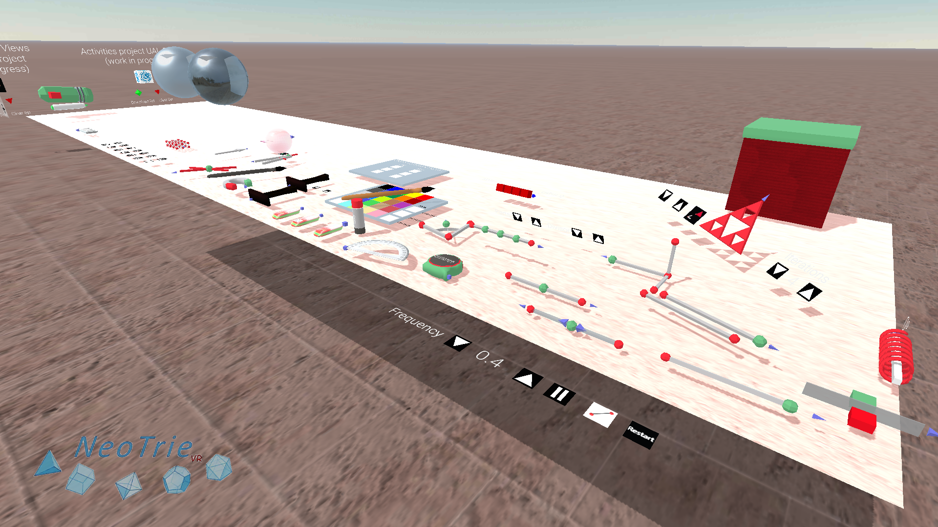

Tools can also be obtained from Menu>Tools.

Tools help: Grab a tool to show how to use it.

Play the corresponding video.
Measuring

Tape
Measure lengths between two vertices, or any two different places.

Protactor tool
The protractor tool gives the angle between two edges, and the dihedral angle between two faces. While maintained the trigger button pressed, touch over two edges or two planes.

Recall that in the quick access Menu, the measuring info button gives the length, area and volume of all the figures in the scene.

The info button shows the number of vertices, edges, and faces, as well as the Euler characteristic (V-E+F).

The label tool can be used to have measures of geometrical elements. Move the tip of the label tool closer until it turns yellow. Then press the trigger button.
See more uses of the label tool below.
Editing tools

Palette and pencil
With the pencil you can paint free drawings, vertices, edges and faces, and other objects inside the scenario. Tool button allows to paint all vertices, edges and faces of a figure.

Optional button that allows you to paint all the similar elements of a figure at once.

Optional button that allows you to paint the faces of a figure with the same number of vertices.

Automatic change of colors
Choose an old and new color to be changed in all the faces of the scene.

Marker
Draws on any surface.![]()

Rubber
The rubber ("eraser") can be used to delete a figure, by touching any of its vertices.

Selector tool
This tool can hide a selection of vertices and edges (touch menu button when taking the tool). It can also be used to rotate or reflect a selection of vertices.
Transforming tools

Copy tool
Press on a vertex of a figure to be copied. The copy tool also allows to make clones of any other figure, 3d object, image, 3D ball, sounds or music notes, free drawing, and any other tool. All these clones can be saved in your scene as a neot file.

This optional button allows you to save a figure in NeotrieSaves>000_MyFigures

Scaled Copy tool
Change the scale to have a scaled copy of a figure or object.
Optional button allows to scale the figure directly.

This optional button allows you to scale the figure directly (without copying).

Rotation tool
Touch 2 vertices or 1 edge, to fix the rotational axis, or a face to rotate around this face.
Button allows to automatically rotate the figure.
Optional tool button allows to make rotated copies dependent from the original.

Reflection tool
- Planar symmetry: Touch one face (or 3 points) and one vertex of a figure to reflect.
- Axial symmetry: Touch one edge (or 2 points) and one vertex of a figure to reflect.
- Central symmetry or inversion: Touch 1 point to fix the center and an extra point of a figure to reflect.
- Optional Button to make dependent reflected copies.

Magnet tool
This tool allows users to join tiles by two of their edges. It also joins two 3D figures by two of their faces, or two pairs of edges.
Your content goes here. Edit or remove this text inline or in the module Content settings. You can also style every aspect of this content in the module Design settings and even apply custom CSS to this text in the module Advanced settings.

Connector
Touch one grabable object and then a figure or object to link it to it when you move the second.
Creating tools

Parallel tool
Use this tool to make parallels, sum of two vectors.
Optional button allows to make parallel copies of figures.

Perpendicular tool
Use this tool to make perpendicular of two vectors, and also projections of a point on a line or plane.
Touch a point on a plane and then the plane to find the perpendicular on that point.
Touch a point on an edge, and the edge to get a perpendicular plane on that point.
Optional button fixes a face for plane geometry.

Middle point tool
Use this tool to make the middle point of a set of points.
Touch an edge or a face to get their middle point.

Divisor tool
Use this tool to have rational points m/n on a segment.
Touch a point of a figure to get divisions of all its edges at once.

Bisector tool
Touch two edges to bisect.

Unlink tool
This allows you to forget any dependence of a vertex from others.

Intersection tool
Intersection tool permits to find the intersection of:
- 2 lines (gives two points of minimal distance).
- 1 plane and a line (touch a plane and then a line, or three lines)
- 2 planes (touch either: two planes, or 4 lines).
- Intersections between other figures are work in progress.

Slider tool
This tool allows to automatically move a point passing through a set of vertices.
Press the button "circle" to generate a circle. Maintain the trigger button press and touch three points: the first one is the center of the circle, the second a point on the circle, and a third to define perpendicular to the plane.
Press the button “restart” to restart all the moves made with the slider tool.

Loci pencil
Use this pencil to draw the trace of a point or edge.

Compass tool
- It transfers a specific distance in a given direction, by selecting 4 points (the first two give the distance, and the last two the direction).
- It finds a point in the intersection of two spheres and a plane, by selecting 5 points.
- It intersects a sphere with a line (by selecting 2 points and an edge).
Compass Extended
- Case 1: Circle passing through 3 points (touching the circle gives also the center);
- Case 2: Touching 3 points: the first one is the center, the second gives the radius (distance to the first), and the third point gives the normal direction from its center.
- Case 3: Circle on a plane given by a center, a point on the circle, and an extra point to fix the plane containing the circle.
- Case 4: Arc between 3 points and a 4 point which fixes the normal direction to the circle.

Sphere tool
Use this tool to make spheres, cylinders, and cones depending on vertices.
Ortohedron
Use this tool to make an ortohedron with or without faces, with the given measures.
The faces will not be assembled.
This optional button will create an ortoehedron with faces.

This optional button will create an ortoehedron with 2 colours.

Nets generator tool
This tool allows to generate a unit cell, as well as crystal structures. Change the parameters a, b, c, alpha, betta, gamma, and size number, to get the desired cell unit.
1. Touch one point and release. This gives you the four points of the unit cell. Create edges if you like.
2. Once you have the cell unit, touch the 4 points generating the cell unit to generate the base net.
3. Finally, touch the previous 4 points and one more single point "atom" to generate its copies.

Fractal tool
Use this tool to build self-similar fractals.

Touch a figure with the set of positions of the selfsimilar copies of the 1st iteration, and then a point of the figure to fractalise.

Touch the origins of the set of frames defining the similarties (affinities), and then a point figure to fractalise.

Touch the 4 vertices of every frame defining the similarties (affinities), and finally a point figure to fractalise.

Point on surface:
Touch 3 points to fix the positions of the origin and the extrems of the intervals U an V of the current formula in the Graphying calculator.
Touch one extra point to draw the image in the surface.
Tilings and projections
The optional buttons of the parallel, rotation and reflection tools are designed to make tessellations with different symmetries. The reflection tool also gives you orthogonal and pointed projections.
Translated copies
Chose 2, 3, or 4 vertices and a point of a figure to make 1, 2, or 3 directions to tile.

Rotated copies
Chose the angle and the number of copies.

Reflected copies
Generates a reflected copy (central, axial or planar).
The reflection tool as a projector:

Generates the reflected copy on a plane.

Projects a figure on a plane from a point.
The pencil, loci pencil, selector, etc. have this optional button to paint the related copies.
3d graphying calculator

3d axis and labeling
The label tool is used to get additional information about our geometric elements. It is also used to create texts, copy and paste from one label to another, and other game options.

Labeling geometrical elements:
Use the label tool to add:
- Name, coordinates to vertices (with respect to the Axis of coordinates).
- Name, weight, length to edges
- Name, area, equation to planes.
- Similar information to circles, spheres, cylinders, cones, etc.
Button true or false for test activities
In the next video, it is shown how to use the label tool to make tests in VR, with scores.
Each label created in the scene can be edited by touching the little red square on its right. One can add the desired text, and also the following commands:
<button correct=t> and <button correct=f> for true or false.
<nhits> for number of hits, <nerrors> number of errors.
One can also edit the file directly with any text editor. For example in this NEOT file one can change texts, positions, and values of buttons ((t=true, f=false).
Buttons to link to other scenes
We can use objects as "doors" to other scenes. Use the label tool, touch on the air or on any object (jpg, STL, OBJ), and then insert <button loadfile=test1> to link to the file test1.neot when it is touched.
Multiview projections

Press the "On" button to turn on the multiview planes.
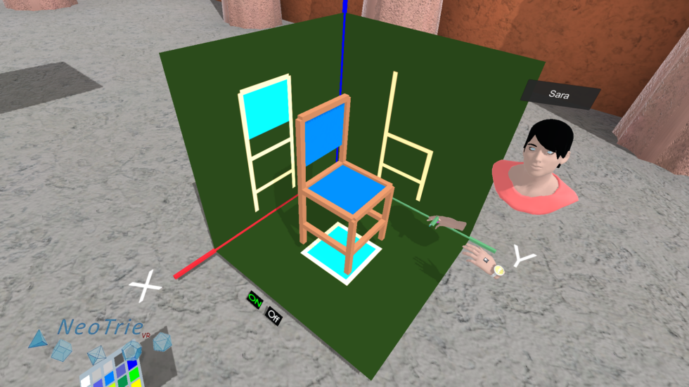
Capture the projections as JPG files in the Projections folder.
Scanner

Press "On" to turn on the scanner, and see the projections of any figure.

Hide the figures allows you to play the game of discovering the hiding figure.

The button "Cut Figure" allows you to see only the sections of a figure.
Gadgets

Boxes (Deleted from version 4.6.3)
Ask your pupils to classify polhyedra or any set of figures by types. One can use these boxes to move a set of figures at once. Boxes are editable, scalable, coloreable, and one can make copies with the "seal" copy tool.
Tool not available in versions 4.7.x

Shuttle
Shuttles can be used with interesting didactical applications. Both the shuttles and the balls are scalable and paintable. They interact with objects. The larger the gun, the larger the balls.

Music boxes
Combine geometry and music, by touching the music balls with your hands (or free drawing, objects, balls of the shuttle, etc.). Make any object sound with any chosen waw file. Use the automatic sliders to move vertices, edges or faces that can touch musical objects to get melodies and rhythms.
Other settings

Config files are useful to configurate your scenes for activities or lesson plans.
Download an example of file.config here.
Open it with any text editor. (Recall to save it as filename.config and not as filename.config.txt). Take care to save it as filename.config (and not as filename.config.txt).
Choose the tools that you want to see on the scene, indicating TRUE or FALSE. Other parameters of the game can also fixed here.
- T_ROTATION = TRUE (indicates that the rotation tool is enabled in the scene).
- MAX_ANGLE_TELEPORT = 10 (indicates the maximum angle of 10º when teleporting).
- VERT_DETECTION_DISTANCE = 0.03 (distance of 3cm to detect any vertex).
These config files have to be located in any folder inside [Documents>Neotrie, for instance:
Documents>Neotrie>Config
You can have as many config files as you like, naming them differently, and maintaining the extension .config. They can be loaded from the new loading menu. In the PC Version, pressing the key "C" loads the default file.config.
One can automatically upload a config file when loading a scene. For that, include the following line in the corresponding neot file. Must indicate the exact route to the config file:
ConfigFileRoute = [documents]/Neotrie/directoryname/.../namefile.config
The lines starting with FILE in the file.config, indicate the route to load the corresponding neot file, when you press the key F+nr. For instance:
- FILE0= file0
- FILE1= /mydirectory/namefile1
In this case, the keys F+0 will upload
[documents]/neotrie/file0.neot
and the keys F+1 will upload
[documents]/neotrie/mydirectory/namefile1.neot
Credits:
- This guide is authored by José L. Rodríguez (University of Almería)
- Software developed by Diego Cangas and Rubén Sánchez (Virtual Dor)
- Editor: Ismael Martos (Marketing, Virtual Dor)
Any reproduction of text, images and videos without prior permission of the authors is prohibited.